Stýrikerfi
Reverse engineering a phone and writing a kernel from scratch
Intro
Stýrikerfi is Icelandic for operating system. It is the incredibly innovative name we ended up dubbing our operating system.
However, let’s take a step back and start at the beginning.
Operating Systems 1 is a mandatory class at my university. I took this class very successfully, and also found it very interesting. Naturally, I then considered taking the optional course Operating Systems 2. As opposed to being only a lecture with an exam, OS2, like other classes, is half-lecture (with an exam) and half-project. Importantly though, the class project is relatively open to choice. The teaching team does present several suggestions—enough that all groups could take one—, but one can just as well come up with their own project and have it approved.
I got together with two of my friends, and we pitched this:
- Take the Siemens S45 mobile phone from 2001.
- Understand how it works internally with very limited documentation and little available prior software.
- Make an operating system, implementing the concepts we had learnt in OS1.
I will admit, many aspects of this journey were uncertain. The instructor who had to approve of the project was rightfully sceptical. But he agreed under the condition that we would update him weekly on our status so that he could gauge whether we would end up with achieving anything presentable.
Thus, we got to work.
Preparation
Eastern European ROM hacks
Before we could even begin dreaming about our operating systems, many aspects of our chosen hardware still needed clarification. We knew that the Siemens S45 is susceptible to some injection during bootstrapping such that code is read from the phone’s serial port and subsequently executed. We found a 10-year-old software project “FREIA” that utilises this to arbitrarily overwrite the phone’s flash memory, including ROM, and even a corresponding GUI application called V_Klay. Thank you, @siemens-mobile-dev. In this way it could, for instance, start executing custom instructions and thus a custom OS. It is for this reason that we chose this specific model in the first place since we knew that we could feasibly get the phone to execute something made by us.
SIEMENS documentation
What we did not know, however, were the instructions supported by the CPU or any other functionalities of it, the memory layout and how to address it, or anything about any of the devices on the board. Luckily, the same niche crowd of Eastern European Siemens enjoyers responsible for the two projects mentioned above had also shared two noteworthy Siemens documents. It was there that we could start our investigation.
Within the little documentation we did find some architectural diagrams granting us first insights. I would show them to you, but I suppose distribution of copyrighted material is illegal… They included that the phone runs on the Infineon C166CBC CPU, which is connected to several RAMs and ROMs and, further, two sticks of flash memory via various buses and so on. Additionally, the documents included some specifications of a CPU closely related to the one in question (we would rely on this spec from then on and always hope that it is applicable) as well as the instruction set of the actual CPU.
Exploring the phone
Now, we did not have access to any assembler that could assemble the instructions listed in the ISM to opcode… So we wrote one ourselves.
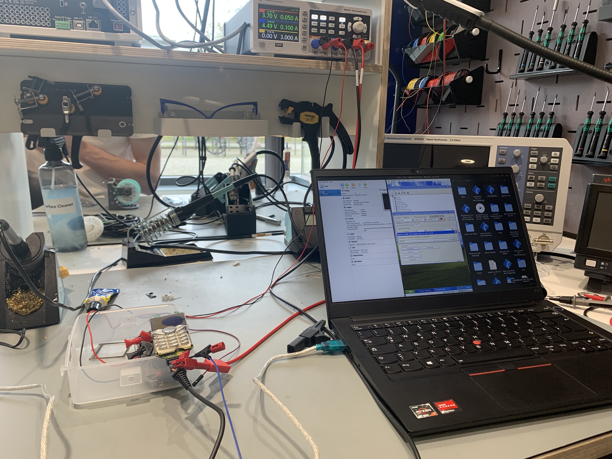
Given these tools, we could start testing out simple programs on the chip. The picture atop is taken from one of these early sessions. They go as follows:
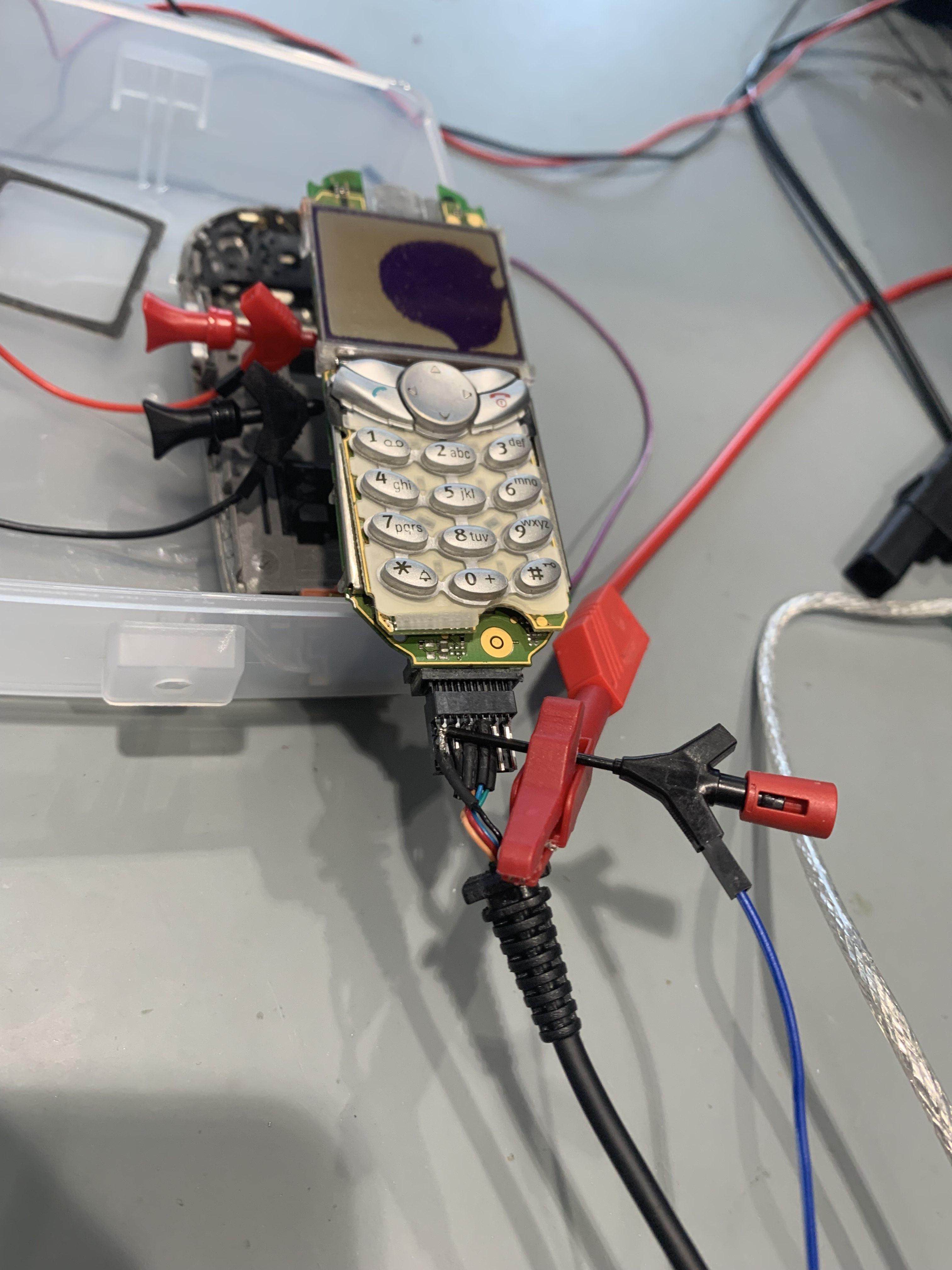
- Of course, we first write a script in our self-made assembly language, which is then assembled to the instructions specified in the ISM.
- We hook up the exposed power pins of the phone to an external power supply since we did not have a battery in place.
- We connect the phone to a laptop via the phone’s proprietary serial cable.
Now come the interesting steps.
- The serial port only works when supplied with 4.5V which it typically draws from the PC once the phone is up and running. However, we want the serial port to read code before the system boots. Therefore, we dismantled the cable and supplied the voltage to the wires from the external power supply.
- As the port is now working, we can use the aforementioned V_Klay to overwrite the entire flash memory before booting. Well, before that we have to boot into our Windows XP VM since that’s the only system for which V_Klay is available…
- Finally, we can wait for several minutes while the V_Klay tool performs a full read and write cycle of the entire flash memory (regardless of how much data we actually need to transfer).
For many weeks this was our only testing workflow. We would write several assembly scripts throughout the week, try to get them right the first time by thinking long and hard. And then we would get together and flash them onto the phone to actually try them out. An emulator would’ve been helpful. But, alas, there is none available.
We wrote a simple CLI program to interact with the phone’s serial interface, most crucially to receive outgoing data and display it in hex. Crucial because, at this stage of the process, it was the only way for us to receive output from the phone at all. We were far (as in, really far) from driving the monitor or speakers or any other device in the phone. In the manual, we only found the output registers, which are transmitted via serial port, and so we dumped all our data there.
However, early on we encountered troubles regarding the baud rate of the interface. Eventually, we managed to align it and reliably receive data from the phone.
Once this hurdle was cleared, a bigger obstacle dawned. The watchdogs on the CPU. A watchdog is a hardware system meant to protect the system in case of critical faults. If the watch dog times out without receiving a signal (“being tickled”), it shuts down the CPU. The documentation we had did warn us of such a watchdog. It also specified an instruction to deactivate it… it did not work. Or did it? It turns out, there is more than one watchdog.
Naturally, you would expect that a functional bootloader such as FREIA somehow executes something which keeps the watchdog from turning off the CPU. So we dug through FREIA’s code to find a configuration of CPU timer 3. This timer was set up to count down three seconds. Its interrupt routine included toggling the bit P4.1 and resetting the timer. Very curious… Presumably, toggling P4.1 is tickling the dog. Let’s copy that timer configuration into our code and start sending bytes on the serial port to see how long it lasts. Result: three seconds. The CPU shuts off after three seconds.
It turns out that the phone can run in one of two frequencies depending on where the instructions are being executed from. Apparently, our CPU was running at the other frequency compared to FREIA. Meaning, the timer also counted at a different frequency. The watchdog’s timeout, however, is at a constant frequency somehow… So ours were misaligned. We figured our timer ran too slowly, and the watchdog timed out before being tickled.
To verify we were being too slow, we made the timer very quick. Suddenly, the system turned off instantly—even before the three seconds had elapsed.
Apparently, the watchdog requires tickling in windows of approximately 0.4 to 3 seconds. Finally, we managed to tame the dog.
Eventually, we built a program which actively read data from the serial port until receiving a terminating byte, wrote the data to memory and executed them as instructions. We flashed this program to the phone as a boot hook. Subsequently, we could supply testing software via the serial interface, which was quickly read and executed. No need for either V_Klay or a full flashing cycle. This made testing and development significantly more convenient, which is why we named it PEACE (Persistent Environment for Arbitrary Code Execution). Hence, we had achieved PEACE. In fact, at later stages of the development, we would send our entire OS image via PEACE for testing purposes.
In a very slow process we gained more and more insight into the phone.
Some details about the phone
The memory layout is a Von Neumann architecture with a 24-bit linear address space. But the CPU registers are only 16 bits wide, and so the instruction set also only allows for 16-bit immediates. How then does one target a 24-bit address? The solution are the so-called Data Page Pointers. Which are explained in this diagram:
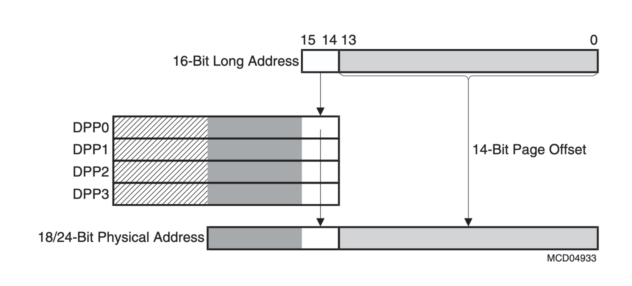
This shows how the first two bits in a 16-bit long address actually specify one of the four DPP registers. That register holds another 8 bits which are then combined into the 24-bit address. More precisely, the DPP acts, as the name states, as a pointer to a page of memory. The last 14 bits of the 16-bit address specify a 14-bit offset within that page. Each page is thus 16 KiB large. Having a paginated address layout is actually quite convenient.
As I have mentioned, there are several units of RAM in the phone. They are combined into this uniform address space. Reading and writing from RAM was not so straightforward, though. Frankly, sometimes we did not know what was going wrong. Ultimately, we settled for utilising the SRAM predominantly for simplicity’s sake. This is a 512 KiB RAM located at 0x100000 to 0x17FFFF. This area holds the pages 0x40 to 0x5F.
Lastly, the CPU’s instruction set follows a convention of maintaining two push-down stacks: both a system stack and user stack. The system stack is specifically in the third page of memory, which is in the IRAM. The registers STKUN and STKOV (stack underflow, stack overflow) delimit the stack bounds. All stack instructions like call, push and pop use this stack. The user stack, on the other hand, can be anywhere in memory. Conventionally, it is addressed through the r0 general purpose register, and it is supposed to be used for stack allocation in programming, like defining variables.
Operating System
Having achieved PEACE and some understanding of the hardware, the time came to make an operating system. The course is called Operating Systems 2, after all. We thus took a step back from the hardware and devised a plan.
Here, our design philosophy came down to keeping it simple. Since we were writing assembly for limited hardware and with many unknowns, implementing any sorts of fancy data structures or algorithms was infeasible. You have to keep in mind that we had to achieve a presentable OS by the end of the semester, which, at this point, was halfway over. Implementing anything in these circumstances is a challenge. Our instructor told us in the beginning that scheduling two processes on the system would be enough to qualify for a final presentation. This was our bar.
Memory organisation and system structs
Our first consideration was the layout of the memory. As mentioned, we decided to focus on the SRAM for our memory utilisation. So we divided the available address space into necessary chunks.
Alongside this came one of our most important decisions. I just explained that our design philosophy was to keep things stupidly simple… Consider this: if a process wants to be executed, it has to be assigned some exclusive real address space so that it does not collide with other processes’ memory. Now, how do you decide which process is given how much memory and where if you don’t know how many processes are going to exist? Don’t get smart on me here; that was a rhetorical question. And the answer to that question is: 8 processes upper limit. We simply decide that no more than 8 processes can exist at once.
Yes, I will admit that this is an incredibly limiting decision from a system perspective. Desktop computers are running hundreds of processes at all moments. However, it would just be easier this way. I want to see you implementing the relevant data structure in assembly.
Additionally, to successfully manage several processes, their states and resources, an operating system needs to take some notes along the way.
The result is this general memory organisation:
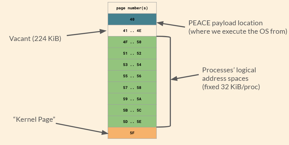
The kernel page is where our kernel writes to in order to keep track of business. It has the following fields:
| Offset | Contents |
|---|---|
| 0000 | PCBs |
| 0200 | Last scheduled PID |
| 0201 | Next candidate PID |
| 0202 | System uptime |
| 1000 | syscall dispatch table |
| 2000 | Process system stacks |
I will get into the use cases for most of these fields in a moment.
“PCBs”, or process control blocks, are blocks of information regarding each process on the machine. The field for PCBs can hold up to eight PCBs, each of which looks like this:
| Contents | Size (Bytes) |
|---|---|
| Code Segment Pointer | 2 |
| Instruction Pointer | 2 |
| Program Status Word | 2 |
| System Stack Pointer | 2 |
| General Purpose Registers | 32 |
| Data Page Pointers | 8 |
| Status | 2 |
| Status Meta | 4 |
These are the system information relevant to the execution of a particular process. They form part of what is called a process’ state. When a context is switched, all of these must be loaded into the correct registers to ensure that the process may function correctly. Only the status and status meta field are for the kernel’s use and not the user process’s.
Scheduling
As for our scheduling algorithm, we settled on preemptive round-robin scheduling without priorities. Again, that is pretty much as simple as it gets.
Our scheduling is driven by CPU timer 3. Now, if you are (still) paying attention, you might notice that I mentioned that we used this timer for tickling the watchdog. At first, we did do that. We switched the tickling to timer 2, since timer 3 is a more precise timer and scheduling occurs at a much finer scale. For comparison: the watchdog needs to be tickled every 0.4-3 seconds, while the quantum of our scheduling algorithm is 8 ms.
Let’s do a quick run-down of how it’ll look.
First, T3 runs out and triggers its interrupt routine, which we have defined as the schedulerInterrupt. This stops the timer (since it would immediately start again otherwise), and then calls the function saveCurrentContextToPCB. I was just talking about the PCB. So you can imagine that this entails going through all registers, whose values correspond to fields in the PCB, and copying them to it. Through this, the state is saved. Additionally, the entirety of the system stack is saved, also to a fixed buffer in the kernel page. Et voilà, the context of the process that is about to lose CPU access has been saved. The user stack does not have to be saved since every process maintains its own user stack.
In round-robin fashion, the scheduler fetches the currently running PID from the kernel pages and increments it by one. It checks whether that process is ready to run, and if so, chooses it. Otherwise, it keeps iterating. We do not specifically have a queue for ready threads, since we can only have eight processes anyway.
When the next ready process has been found, the scheduler updates the kernel variables regarding the current PID. It then calls the dispatcher.
Dispatching and context switches
And here it comes! Basically, the previously described state saving routine is being executed in reverse. We restore the system stack from the kernel page buffer to its location in IRAM. Then we copy all values found within the PCB of the (soon-to-be) newly running process to their corresponding registers. Lastly, the dispatcher returns to the scheduler routine. This pops the CSP/IP from the system stack, which is now in the state that the new process left it in when it was last executed. Thus, returning to the popped values brings the execution flow right back into the new process—wherever it left off. It, thus, runs.
This cycle simply repeats every 8 ms. In this way, all active processes get an equal share of the CPU. Due to a lack of priorities, starvation cannot occur.
System API
Operating systems usually implement a system API to allow user-level processes to request actions regarding any resource managed by the kernel. A common example would be allocating and freeing memory. Now, we did not end up writing a heap allocator. We did start one but could not finish it in time. Nevertheless, there are system functions worth exposing.
They are as follows:
| Syscall number | Function |
|---|---|
| 0 | CreateProcess |
| 1 | TerminateProcess |
| 2 | (reserved for malloc) |
| 3 | (reserved for free) |
| 4 | Serial0::txWord |
| 5 | Serial0::txByte |
| 6 | Serial0::rxByte |
| 7 | Serial0::rxBytes |
| 8 | WaitForProcess |
| 9 | Serial0::txUIntBase10 |
An application can perform a syscall by writing the desired syscall’s number to a specified register and then triggering a specific trap. This trap calls an interrupt routine which fetches the syscall number and looks it up in the syscall dispatch table in the kernel page. The table holds the address of the syscall’s routine so it can be executed. In case the syscall expects an argument, it can be supplied to the conventional r1 register by the application.
For example, sending a base-10 ASCII string of the character 2 to the serial interface looks like:
mov r1, 2
mov r15, $SYSCALL_txUIntBase10
trap 0x50
Here, $SYSCALL_txUIntBase10 has previously been defined as an alias for the number 9 to improve legibility in this context.
Fun fact: there actually is no separation between user and kernel space in the C166 CPU at all. Every application can access all resources and our OS cannot prevent that. We implemented syscalls mostly because we felt that a good OS needs to have some.
Simple shell and user programs
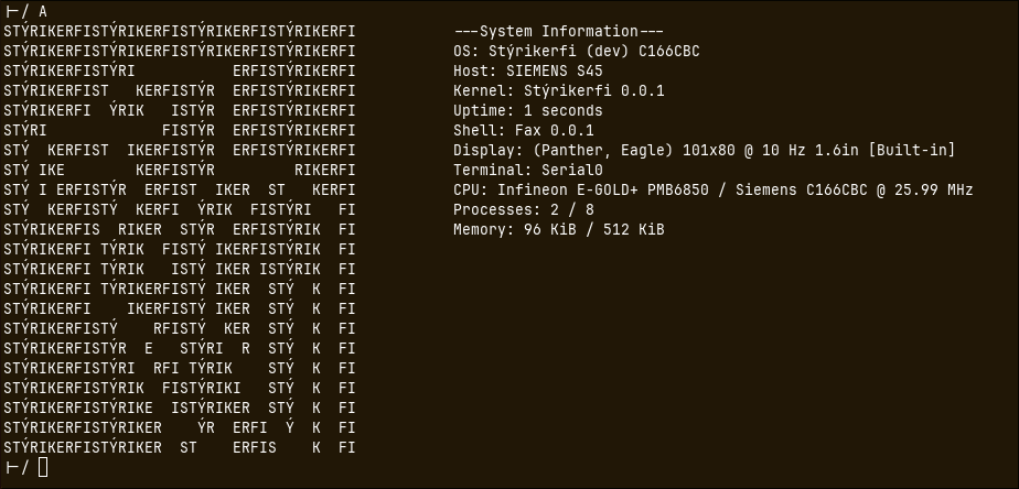
Tada! A shell running a fetching program. Famously, that’s all you need for the true terminal experience.
This shell ended up being our main interface with the phone. We did not end up achieving any device drivers during the limited time we had. The serial port is all I/O we have. So we wrote a shell program in assembly that could take arguments via the serial port, as well as a Python script for the PC that could communicate with the serial port and print the output to the laptop screen.
Through the shell, a couple proof-of-concept user programmes can be executed. Some can even be supplied with an argument.
Also, the shell relies on another process status, which is actually where the status and status meta fields of the PCBs come into play. When the shell launches a program, it is set to the waiting status, and the status meta stores the PID of the process that the shell is waiting for. While waiting, the shell is only scheduled once the process it is waiting on is no longer ready. Therefore, the shell consumes no resources until the called program returns to the shell.
Aaand that’s pretty much it! Our own little operating system, written entirely from scratch for an archaic, undocumented, proprietary phone.
Miscellaneous
Compiler
Towards the end, we also wrote our own compiler in Rust to create those proof-of-concept applications, thus, inventing a second programming language for the project :D
We just could not get a hold of one otherwise, you know. ¯\_(ツ)_/¯
Results & Outlook
After our final presentation, whose contents resemble this blog post, plus a live demonstration, we received a 1.0 (A) for the project. The professor seemed very happy with our results.
This has been my favourite project of mine since. That is why it’s pinned at the top of this blog after all.
You can find all of our code on GitLab. The source is open, as it should be. And, hey, if you’re excited about hacking old phones, get yourself a Siemens S45 and keep building on our code.
Actually, at the next iteration of operating systems 2, extension projects on top of our base will be suggested to the students. Building an emulator or a file system. Additionally, we are scheduled to present the reverse engineering side of things at Hacken & Schnacken Vol. 11, a hack & tell event by our student cybersecurity club.